How Engineering Tolerances Affect Performance, Safety and Reliability
Engineering tolerances are often treated as a detail on a drawing, but in reality they define whether a component performs as intended once it leaves the machine.
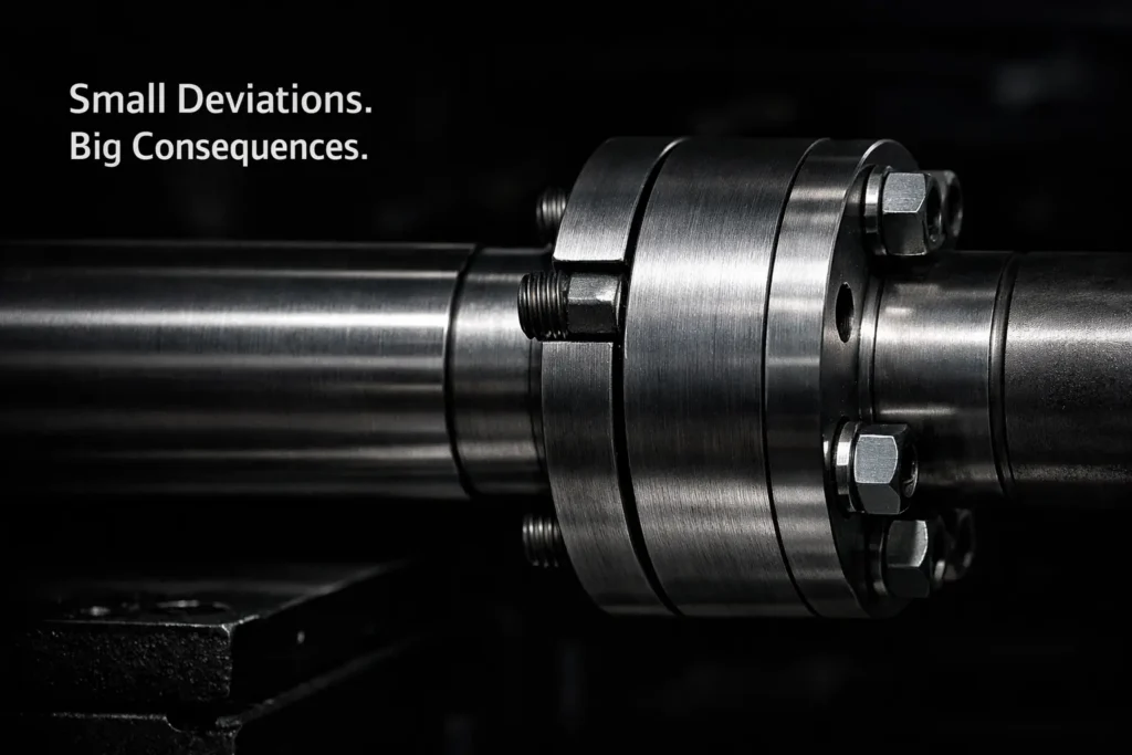
Every engineered system relies on controlled variation. No component is manufactured to a perfect dimension, so tolerances exist to define the acceptable limits within which parts can function correctly. When those limits are exceeded, even slightly, the consequences can range from reduced efficiency to complete system failure.
In many industries, tolerance issues are not immediately visible. Components may assemble correctly, pass initial inspection and even operate for a period of time before problems begin to emerge. This makes poor or inconsistent engineering tolerances one of the more difficult issues to diagnose in complex systems.
Why Engineering Tolerances Exist in the First Place
No manufacturing process is perfectly repeatable. Even the most advanced CNC machining, fabrication and finishing processes introduce small variations in size, geometry and surface condition.
Engineering tolerances define:
- allowable dimensional variation
- acceptable geometric deviation
- surface finish requirements
- fit between mating components
Without clearly defined engineering tolerances, components cannot be produced consistently or assembled reliably. International standards such as ISO’s Geometrical Product Specifications (GPS) framework define how tolerances are applied and interpreted across engineering and manufacturing.
Tolerances are therefore not just a manufacturing constraint. They are a design decision that balances performance, cost and manufacturability.
What Happens When Engineering Tolerances Are Too Loose
Loose or poorly specified engineering tolerances can lead to components that technically meet drawing requirements but fail in real-world conditions.
Common issues include:
- excessive vibration in rotating systems
- poor alignment between assemblies
- reduced load distribution across contact surfaces
- increased wear over time
In mechanical systems, even small misalignments can create uneven stress concentrations. Over time, this can lead to fatigue failure, especially in high-load or high-cycle environments such as rail, automotive or industrial machinery.
Loose tolerances can also affect sealing performance. Gaps that are slightly larger than intended may allow fluid leakage, contamination or pressure loss.
What Happens When Engineering Tolerances Are Too Tight
Tight tolerances are often assumed to be better, but this is not always the case.
Overly tight engineering tolerances can create:
- assembly difficulties
- increased manufacturing cost
- higher rejection rates
- thermal expansion issues
Components that are too tightly specified may not assemble easily, especially when multiple parts interact. In some cases, parts may require excessive force to fit together, introducing stress before the system is even in operation.
Temperature changes can also cause problems. Materials expand and contract, so a tolerance that works at room temperature may fail under operating conditions.
In high-performance systems, this can result in binding, distortion or premature wear.
The Risks of Not Meeting Engineering Tolerances
When engineering tolerances are not achieved consistently, the impact is often cumulative.
Instead of a single failure point, systems experience:
- gradual performance degradation
- increased maintenance requirements
- reduced operational efficiency
- unexpected downtime
In safety-critical sectors such as defence, aerospace and rail, tolerance failures can have far more serious consequences. Misalignment, poor fit or unexpected stress behaviour can compromise structural integrity or system reliability.
This is why tolerance control is closely linked to quality assurance, inspection and validation processes.
Engineering Tolerances and Surface Interaction
Engineering tolerances are not only about dimensions. Surface condition plays a critical role in how components interact.
Surface roughness, coating thickness and material finish can all influence:
- friction
- wear rates
- electrical conductivity
- corrosion resistance
Two components may meet dimensional tolerances but still perform poorly if their surface characteristics are not controlled correctly. This is particularly important in electrical systems, where contact surfaces must maintain consistent conductivity over time.
Processes such as electroplating can also affect final dimensions and must be carefully controlled to ensure components remain within their specified tolerance ranges.
Why Tolerance Stack-Up Matters in Complex Assemblies
In complex systems, multiple tolerances combine to create what is known as tolerance stack-up.
Each individual component may fall within its specified tolerance range, but when assembled together, the cumulative variation can lead to:
- misalignment
- interference
- excessive clearance
Tolerance stack-up is a common issue in large assemblies such as:
- rail infrastructure components
- vehicle chassis systems
- industrial machinery
- aerospace structures
Managing stack-up requires careful planning during the design stage, as well as precise control during manufacturing.
How Engineering Tolerances Are Controlled in Practice
Controlling engineering tolerances requires a combination of:
- precision machining processes
- stable material selection
- accurate measurement and inspection
- process consistency
Achieving consistency at scale often relies on processes such as large format machining, where maintaining dimensional accuracy across oversized components is critical.
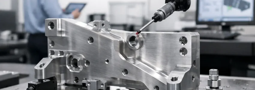
Modern manufacturing environments rely on digital measurement tools, coordinate measuring machines (CMMs) and in-process inspection systems to ensure tolerances are maintained.
However, tolerance control is not just about measurement. It also depends on how components are produced, handled and finished throughout the manufacturing process.
The Role of Process Selection to Meet Tolerance Levels
Different manufacturing processes affect tolerances in different ways.
For example:
- machining processes influence dimensional accuracy
- cutting methods affect edge quality and distortion
- finishing processes affect surface condition
Choosing the right process is therefore critical.
Processes that introduce heat, stress or distortion can make it more difficult to maintain tight tolerances. This is why certain applications favour cold cutting or controlled machining techniques to preserve material stability.
Engineers often compare cutting methods depending on accuracy and distortion, which is why waterjet cutting is sometimes chosen over laser or plasma cutting.
Why Engineering Tolerances Are a Design Responsibility
Engineering tolerances are not simply passed down to manufacturing. They originate in design.
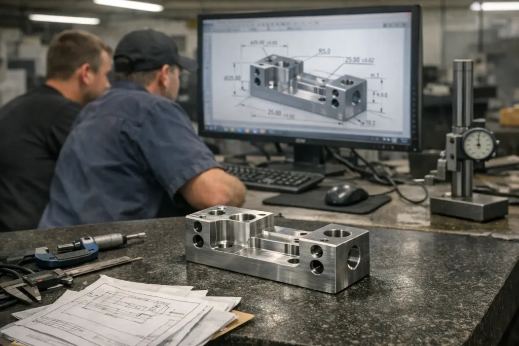
Design engineers must consider how components will be manufactured. how materials will behave under load, how assemblies will fit together and how systems will perform over time.
Poorly defined tolerances can create unnecessary complexity during manufacturing or introduce hidden risks in the final product. Effective tolerance design requires collaboration between design, manufacturing and inspection teams.
How PRV Approaches Tolerances in Critical Applications
In many of the sectors PRV supports, engineering tolerances are not just about performance but also safety, reliability and compliance.
Across industries such as defence, aerospace and aviation, rail, oil and gas, and large-scale construction, even small deviations can have significant consequences. Components must perform consistently under load, across varying temperatures and in demanding environments where failure is not an option.
Maintaining tight and repeatable engineering tolerances in these applications requires more than precision machining alone. It depends on how the entire process is managed, from material selection through to final inspection.
This includes:
- stable and repeatable machining processes
- careful control of material behaviour during fabrication
- selecting cutting methods that minimise distortion
- managing surface condition and finishing processes
- consistent inspection and verification at each stage
In practice, this means understanding how each manufacturing step influences the next. A component that is machined accurately but distorted during cutting or finishing will still fall outside its intended tolerance range.
Final Thoughts on Engineering Tolerances
Engineering tolerances define the boundary between a component that works and one that fails over time.
They influence how parts fit together, how systems behave under load and how long equipment can operate reliably. Whether tolerances are too loose, too tight or simply inconsistent, the effects are often not immediate but become visible through wear, inefficiency or failure.
For engineers and manufacturers alike, tolerances are not just numbers on a drawing. They are a critical part of how performance, reliability and safety are achieved in real-world systems.
By working across multiple sectors and complex applications, PRV’s approach focuses on process control, consistency and practical engineering understanding, rather than relying on inspection alone to identify issues after they occur.
Recent Comments